OEM/ODM Supplier for 3-PCS Locking Pliers Sets surface by Electrophoresis to Sierra Leone
Short Description:
Product Detail
Product Tags
The company keeps to the operation concept "scientific management, high quality and efficiency primacy, customer supreme for OEM/ODM Supplier for 3-PCS Locking Pliers Sets surface by Electrophoresis to Sierra Leone, "Passion, Honesty, Sound service, Keen cooperation and Development" are our goals. We are here expecting friends all over the world!
Basic Information
■Model Number: RL-DLQ023
Additional Information
■Material: A3# steel (Q235) or 45# steel
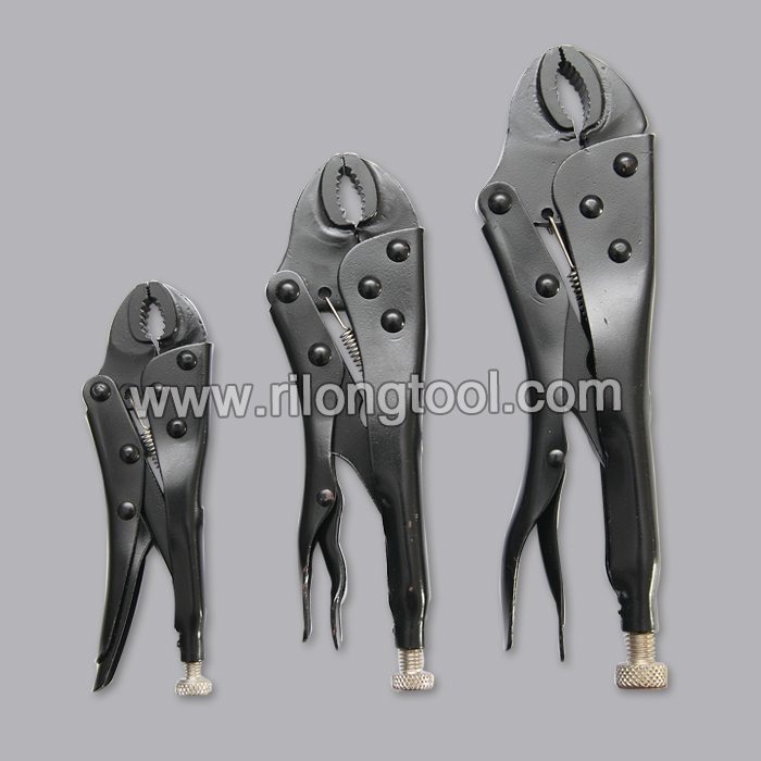
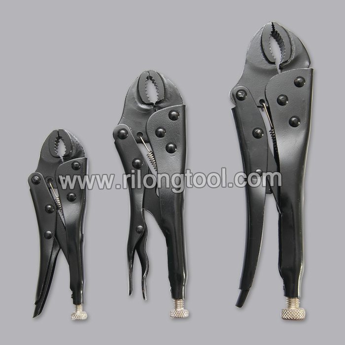
■Size: 5”, 7″, 10″
■Surface Treatment: Electrophoresis
■Heat Treatment: Optional
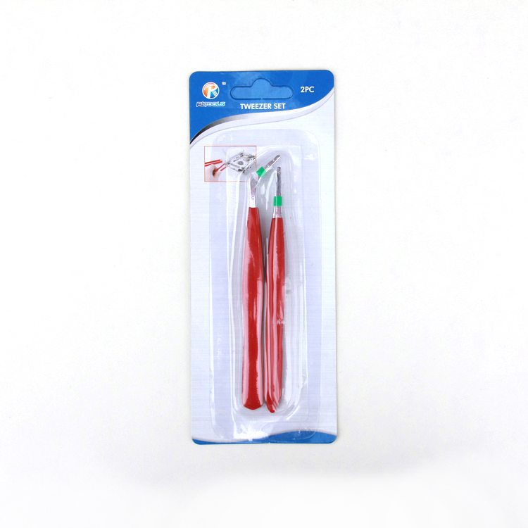
■Package: Blister Card, Suction Card, Double Blister Card
■OEM: Acceptable
■HS Code: 8203200000
■Samples: For FREE
■Delivery Time: Always 30 working days depending on the order quantity
■Packing: By standard cartons
Product Description
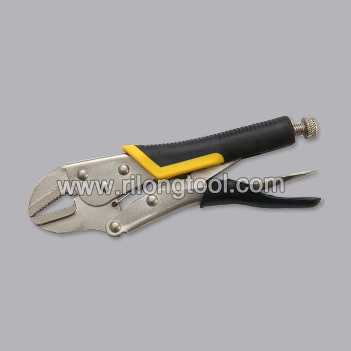
■Mainly used for clamping parts to rivet, weld, grind and so on, which is characterized by the powerful clamp force produced by the jaw. It can lock tight so that the parts won’t fetch away. Besides, jaws have a lot of levels to adjust for the use of different thickness of parts, and it also can be used as a wrench.
■Flexible using, long life and good tenacity.
■The screw tuning button can give the best clamp size easily.
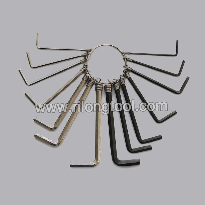
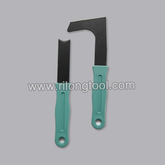
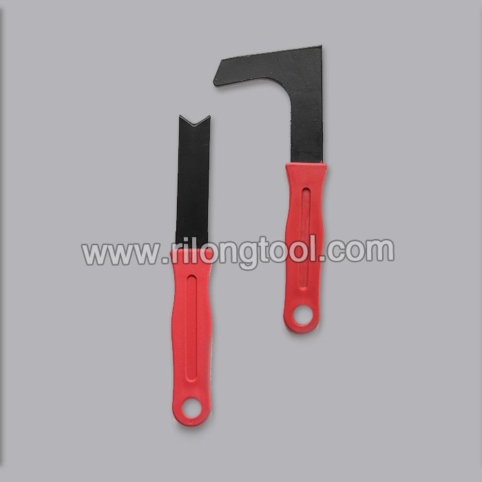
Product Image
Find Motion Pro Stepless Hose Clamps this Dennis Kirk product page: https://bit.ly/x0xKIp
The Motion Pro Stepless Hose Clamps are simpler, more secure and easier to use than screw type hose clamps.
In this Autodesk inventor assembly tutorial we will create a model named ‘Vise’. The tutorial covers assembly modeling concepts, along with basic sketching/part modeling. This is because, the components or parts of the Vise are created individually, not in context or with reference of, other parts of the assembly, which is termed as Bottom-up approach. After modeling it, we will be able to create, dynamic simulation and exploded views of the Vise, for presentation purpose.
The designing process of the model is following….
The vise model has several parts after creating the components individually they are placed into the three sub-assemblies separately by using assembly mates. In the end final assembly is created by placing aforesaid three sub-assemblies.
So in this way viewers will be able to observe the application of many 2D and 3D features of the software in part modeling environment and application of mates in assembly modeling environment.
………………………………………………..
To create the Dynamic Simulation of this assembly visit the following link:–
…………………………………………………..
To create the exploded views of this model visit the following link:-
……………………………………………………………………………………
The finished file displayed in the video can be accessed by visiting the content list of our blog on the following link:—
https://niveshandnisheeth.blogspot.com/2013/03/content-list.html
………………………………………………………………………..
To watch more similar tutorials visit following link:-
https://www.youtube.com/playlist?list=PLKWX3xUP3pPohm1AF7u7lEYfFh7QF1bmz
………………………………………………………………………….
Our motive to upload this video is to show our work ability/experience, so as to get job in the appropriate field.