OEM manufacturer custom 12″ Long Locking Pliers to Tunisia Factories
Short Description:
Product Detail
Product Tags
Our eternal pursuits are the attitude of "regard the market, regard the custom, regard the science" and the theory of "quality the basic, trust the first and management the advanced" for OEM manufacturer custom 12″ Long Locking Pliers to Tunisia Factories, Welcome to visit us at any time for business relationship established.
Basic Information
■Model Number: RL-DLQ016
Additional Information
■Material: A3# steel (Q235) or 45# steel
■Size: 12”
■Surface Treatment: Nickel-plated, Zinc-plated, Black Oxide, Electrophoresis
■Heat Treatment: Optional
■Package: Blister Card, Suction Card, Tie Card, Double Blister Card
■OEM: Acceptable
■HS Code: 8203200000
■Samples: For FREE
■Delivery Time: Always 30 working days depending on the order quantity
■Packing: By standard cartons
Product Description
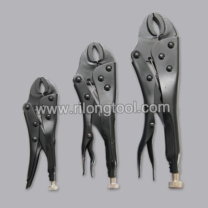
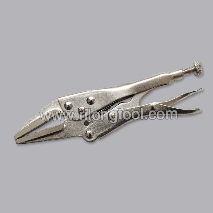
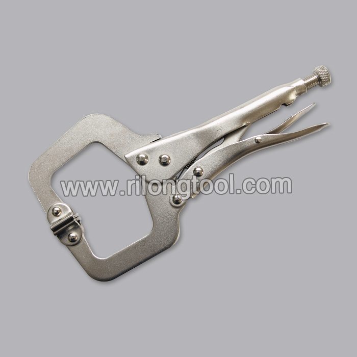
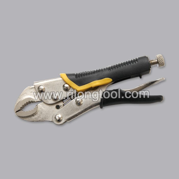
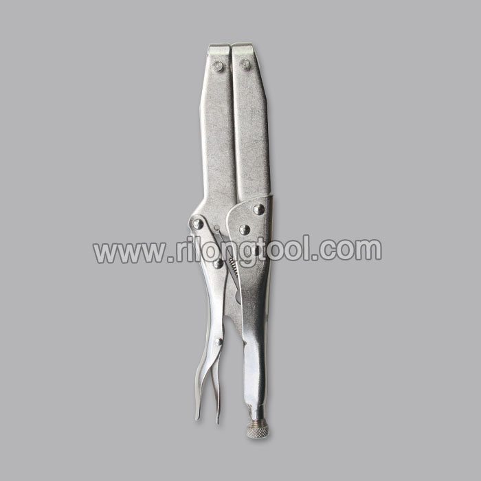
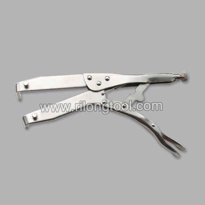
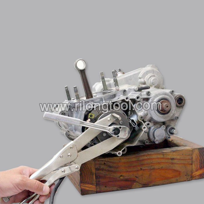
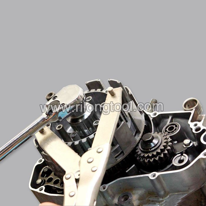
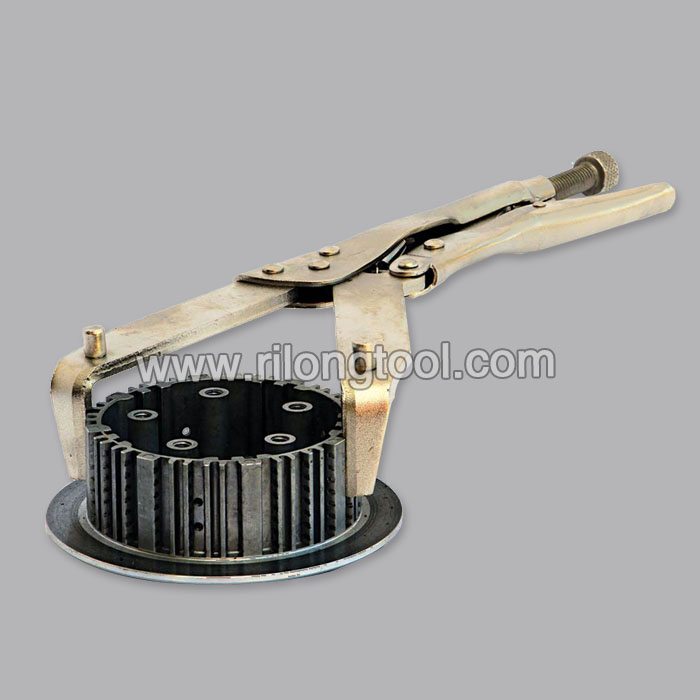
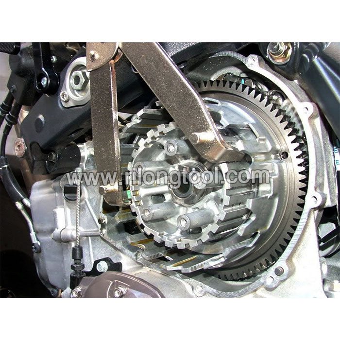
■Mainly used for clamping parts to rivet, weld, grind and so on, which is characterized by the powerful clamp force produced by the jaw. It can lock tight so that the parts won’t fetch away. Besides, jaws have a lot of levels to adjust for the use of different thickness of parts, and it also can be used as a wrench.
■Flexible using, long life and good tenacity.
■The screw tuning button can give the best clamp size easily.
Product Image
https://honda-tech.com/how-tos is the leading Honda Accord and Civic resource for technical DIY guides. The brakes are arguably the most important components of any vehicle. For the step-by-step article, please visit https://www.honda-tech.com/how-tos/a/honda-accord-how-to-replace-brake-pads-calipers-and-rotors-374563
This moderately difficult job takes 4-5 hours and costs $600+. A professional may charge from $1,500+.
This job requires a ratchet and socket set, hub-puller, torque wrench, breaker bar, C-clamp, hydraulic floor jack and jack stands, an off-set 12 millimeter wrench, and an assistant.
If you need to replace the calipers, you will need to drain or siphon the brake fluid from the master cylinder and bleed the brake lines before jacking up the car.
Step 1 – Jack up car
Loosen the lug nuts. Jack the front end up. Set car on the jack stands and remove wheels.
Step 2 – Remove spindle nut and bolt
Use a screwdriver or a nail and hammer the spindle bolt in the void where the metal bends in to make it form a circle so you can pull it off.
Use a 36 mm socket and long handled ratchet to remove the bolt. An air ratchet is optimal.
Have someone depress the brake pedal while you wrench on the bolt and complete Step 3.
Step 3 – Loosen four flange bolts on hub
Break free the four flange bolts on the front of the hub.
Step 4 – Remove two caliper housing bolts and caliper
Use a deep-well socket to work around the brake lines. Remove the bolts, and the caliper will come right off.
Set the caliper aside if it is still good and doesn’t need replacing. Otherwise, you’ll install the new caliper after the rotors are replaced.
If you are going to replace the calipers, you’ll need to bleed the lines at this point. You can use the small vice grips to minimize the amount of fluid to bleed. Use a C-clamp or large channel locks to compress the caliper pistons and force the fluid out the bleeder valve into your container.
In order to replace the caliper, disconnect the brake line by removing the banjo bolt.
Step 5 – Pull caliper bracket
Two bolts hold the caliper bracket in place. When you are removing them, loosen them both first; then, remove the bottom bolt before removing the top bolt, and the entire bracket will pull right off.
Step 6- Remove four rear hub bolts
There are four 12 mm bolts on the rear of the hub that need to be removed. Use an offset wrench. You will have to push the drive shaft protector away to get the wrench in there, and you may need to use some WD-40 or other spray lubricant to help get those bolts loose.
Step 7 – Remove hub
Place the hub-puller over two lug nut screws and screw those two lug nuts back on.
Put the hub puller cross-member on and screw that center bolt down until the hub and wheel bearing pop off.
Step 8 – Grease the wheel bearing and axle end
With the hub pulled, now is the perfect time to give the wheel bearings and axle ends a little TLC. If they are rusty, get some 800-grit sandpaper and get rid of as much rust as possible. Once that is cleaned up, use some multi-purpose grease and lube the wheel bearing, axle, and housing.
Replace the four rear hub bolts.
Step 9 – Put the new rotor onto the hub
Make sure that you are putting the rotor back onto the hub in the correct direction.
Step 10 – Re-install the rotor and hub unit onto the bearing and axle end
Line up the four bolts from the rear of the hub unit with the hub assembly so you can get a bite on those bolts. You will have to play with the bearing to get it in and get those bolts to bite.
Once those bolts get a good bite and are in well, use a rubber mallet and hit the assembly in place until it is in there well. Tighten those four back bolts and use the mallet to hit it some more.
Step 11 – Assemble the new pads and calipers
The hardest part is over. Now it’s time to reassemble everything. Put your new pads into the new calipers. It may be easier to get the calipers back on to the rotor and then install the new pads.
Step 12 – Re-install caliper bracket and calipers
Put the caliper bracket back in place as well as the housing. Wiggle the housing on the rotor, sliding it up and down until the bolt bites. Tighten all the caliper and caliper housing bolts and then torque them to specifications. If you haven’t installed the new brake pads, do so now before you tighten and torque the housing bolts.
Step 13 – Re-install the spindle nut and wheels
You are almost finished. Put the spindle nut back on and use a screwdriver to deform it back into the void part of the drive shaft. Tighten down the spindle nut to at least where the end of the shaft meets the end of the spindle nut. Actual specifications call for about 181 ft.-lbs. of torque.
You will need your helper to step on the brake pedal before tightening. Keep pressing on the brake while you put the tires back on and tighten the lug nuts.
Lower the car off the jack stands and torque down the lug nuts.
Video #1 in the HELP Series on PCTV
The proper use of and how to install Solderless Connectors.
Channellock 909 Crimping Tool
https://www.amazon.com/gp/product/B00004SBDI/ref=as_li_tl?ie=UTF8&tag=allcusparsto-20&camp=1789&creative=9325&linkCode=as2&creativeASIN=B00004SBDI&linkId=49a6f6a5efd2bf9f575d56a431c71fe9
S & G Tool Aid 18920 Ratcheting Terminal Crimping Kit- 5 Piece
https://www.amazon.com/gp/product/B0002STTTI/ref=as_li_tl?ie=UTF8&tag=allcusparsto-20&camp=1789&creative=9325&linkCode=as2&creativeASIN=B0002STTTI&linkId=1c1c14e7f8ed28379e2938f0a48d6859